Article index:
- 1 – Overview of the GPIO Connector
- 2 – The 26-pin GPIO connector
- 3 – The 40-pin GPIO connector
- 4 – References
1 – Overview of the GPIO Connector
The GPIO (or General Purpose Input Output) connector is a great feature of Raspberry Pi boards. Thanks to the GPIO, you can control real devices: the GPIO is the interface with the real world. The GPIO lets you send (output) information to electronic systems made up of LEDs, resistors, transistors or receive (input) information from buttons.
The programming of the GPIO is really simple. In few lines of code, you can get a blinking LED for example.
There are 2 kind of GPIO connectors:
– a 26-pin connector (Raspberry Pi 1 Model A/B)
– a 40-pin connector (Raspberry Pi 1 Model B+ or Raspberry Pi 2 Model B)
The pins can be programmed as general output (for controlling a LED for example) or as general input (to receive the signal from a button). When they are used as output, programmable pins are like switches: they are either HIGH (on) or LOW (off). When a pin is HIGH, it delivers a potential difference (or voltage) of 3.3V.
You have to pay attention to the max current intensity that can be delivered by the pins. This is really important if you don’t want to damage your Raspberry Pi board. According to some documentations, the 3.3V power supply can deliver up to 50mA (or 0.165W which is really low). The intensity of 50mA is the total current intensity for all pins simultaneously. Now, according to HERE and HERE, a single pin can deliver from 2mA to 16mA.
Let’s recap a bit:
– 3 pins with 5mA per pin: OK (15mA)
– 5 pins with 9mA per pin: OK (45mA)
– 3 pins with 16mA per pin: OK (48mA but limit!)
– 5 pins with 16mA per pin: RISK of DAMAGE: 5*16mA > 50mA.
It’s not recommended to draw a lot of current. The Raspberry Pi GPIO is not designed to supply much power and should be use to send/receive information only. That means you have to interface the GPIO and the final device with an amplification stage. You should’nt, for example, directly control a small motor (a fan…) with a programmable pin. To control such a small motor, you should use an interface with some transistors and resistors. The general rule is to limit the current to the lowest possible value (2mA or 3mA or even lower per pin). A value less than 1mA is perfect but requires an amplifier to control a LED or a fan for example.
Power pins (physical pins 2 and 4) can be used to supply voltage to your electronic. The current supported by the 5V pins are more or less limited by the power supply unit of the RPi board. The RPi board requires around 700mA. So if you have a 1000mA power supply unit, the 5V pin can supply up to 300mA. Enough for 10 LEDs or for few cooling fans…
We’ll see in a next article how to create a simple and safe electronic circuit to control a LED.
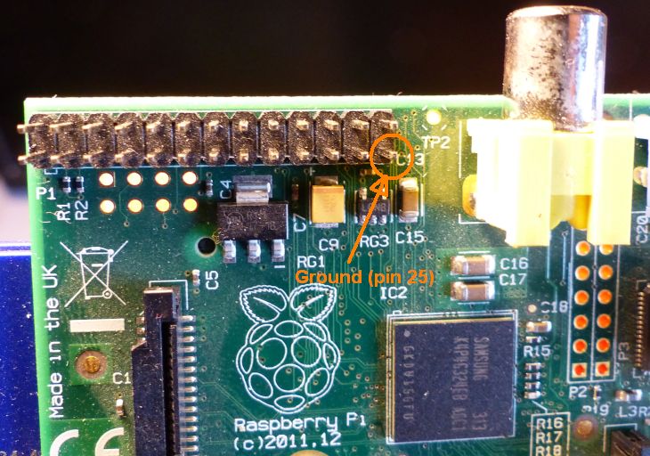
2 – The 26-pin GPIO connector
The 26-pin connector is available on the Raspberry Pi 1 Model A and B.
source
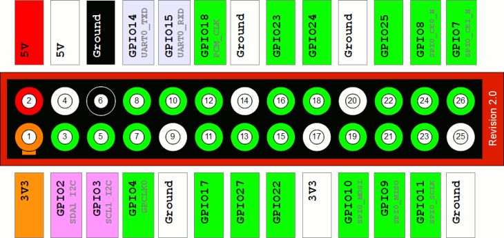
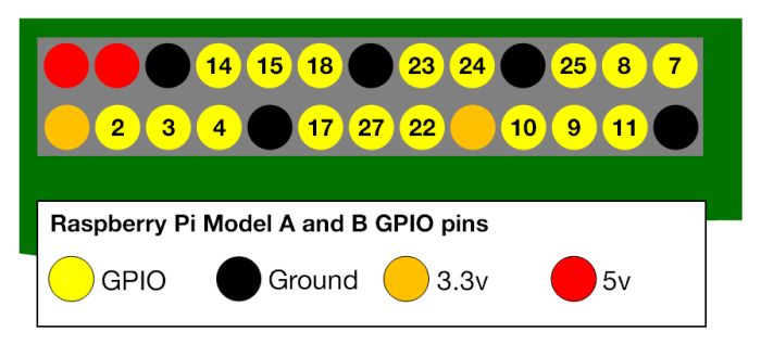
Pin Numbering
As you can see they are several ways to number the GPIO pins:
– the physical way.
– the GPIO way.
The GPIO numbering is used in most of the demos and articles you can read. The following pictures show the relation between physical and GPIO numbering:

source
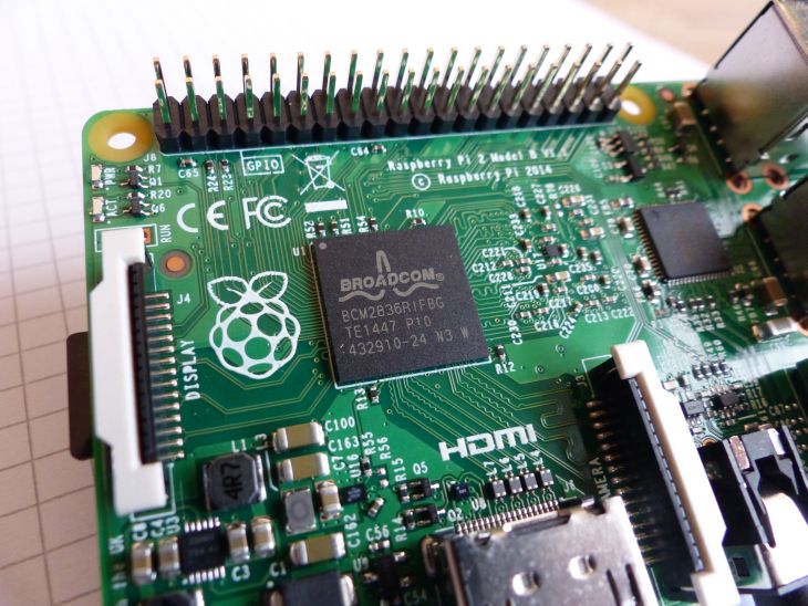
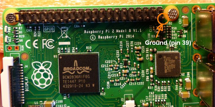
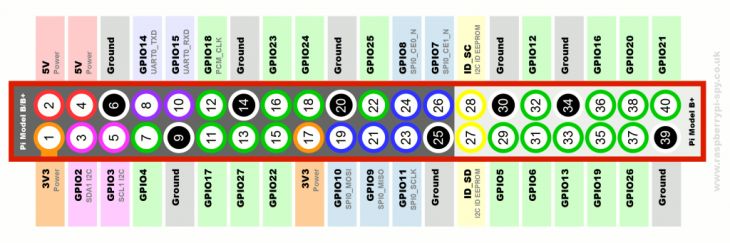
3 – The 40-pin GPIO connector
The 40-pin connector is available on the Raspberry Pi 1 Model B+ and on the Raspberry Pi 2 Model B.
Different type of content from what I normally see on here. Is there going to be a transition to more Arduino/Pi articles?
Probably to more RPi related articles because of the RPi support I added in GLSL Hacker.
If you want to make sure you don’t tax the pins too much use Darlington transistors and other amplifying power electronics.