
Article index:
- 1 – The Hardware Side
- 1.1 – First Circuit: LED + Resistor
- 1.2 – Second Circuit: LED + Resistor + Amplifier
- 2 – The Software Side
This article will show you how to easily turn on and off a LED (the real world) using GeeXLab (the virtual world) and the GPIO connector of the Raspberry Pi (the interface to the real world). The information of this article is valid for Raspberry Pi 1 and 2.
1 – The Hardware Side
To turn ON/OFF a LED, we will use a pin of the GPIO connector. Several pins are available for that particular task. For this article, we will use the pin 23 (in the GPIO pin numbering mode):
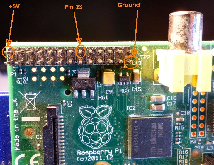 The GPIO connector of the Raspberry Pi 1
We’re going to see two methods to connect the LED to the GPIO: the first one is simple but does not allow to reach the max current in the LED. The second method is a little bit more complicated but is the right way to do things.
1.1 – First Circuit: LED + Resistor
The first and most simple way to connect the LED to the GPIO pin 23 is given by the following scheme:
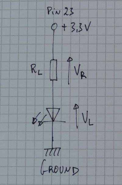
The LED is connected to the pin 23 via a resistor. The goal of the resistor is to limit the current intensity in order to not damage the RPi board as well as the LED. A typical red LED can support a max current of 20mA. But as we have seen in this article, a pin can deliver a current up to 16mA. But it’s not safe to be at the max value. A value of 10mA is enough for the LED and is OK for the pin 23. To determine the value of the resistor, we’re going to use the famous Ohm’s law: V = RI or in our case R = V/I.
When the pin 23 is ON, the voltage between pin 23 and the ground is 3.3V. When it is ON, the LED has a threshold voltage called forward voltage (or forward drop) of 1.8V (up to 2.2V depending on the LED). The voltage across the resistor is:
VR = 3.3 - VL = 3.3 - 1.8 = 1.5V
If we want to limit the max current intensity to 10mA, the value of the resistor is:
R = VR / Imax = 1.5 / 0.01 = 150 ohm
I don’t know why, but I have tons of 470 ohm resistors. Two 470 ohm in parallel are equivalent to a single 235 ohm resistor. With 235 ohm, the max current is: 1.5 / 235 = 0.006 or 6mA. This value is enough for the LED and is perfectly safe for the Raspberry Pi GPIO.

1.2 – Second Circuit: LED + Resistor + Amplifier
This second method is the right way to control the LED. The pin 23 is used to send a signal but does not feed the final electronic device (here the LED). An amplifier stage is inserted in the scheme to amplify the pin 23 signal and feed the LED. The amplifier stage is made up of one of the most simple electronic device but at the same time one of most fundamental components: the transistor.
The transistor has two main working modes: in linear amplification and in saturation. In our case, we are interested by the saturation mode (also called commutation mode). In that mode, the transistor can be seen as a switch. When it’s OFF, no current feeds the LED. When it’s ON, the LED is fed.
The transistor has 3 pins: the base, the collector and the emitter. If the current intensity in the base is greater than a value called Isat (or saturation current) the transistor works in saturation and is like a closed switch. In saturation, we have to take into account two new voltages: the emitter-collector voltage (Vce) and the emitter-base voltage (Vbe).
The electronic circuit to feed the LED with the transistor is the following one:

I selected a 2N2222a transistor. This transistor has a gain around 100 (the gain is also called Hfe in datasheets). That means that if we want 10mA in the LED (10mA is enough to get a bright LED), the current through the transistor base is: 10mA / Hfe = 0.01 / 100 = 0.1mA.
When the transistor is in saturation, the emitter-base voltage is around 0.7V. We can now determinate the Rb resistor at the base of the transistor:
Rb = (3.3 – 0.7) / 0.0001 = 26000 ohm.
I don’t have 26000 ohm resistors but I have a 12000 ohm resistor. With 12000 ohm, the Ib current intensity is:
Ib = (3.3 – 0.7) / 12000 = 0.2mA
With a current of 0.2mA (or 200pA) we are sure that the transistor is working in saturation mode. With a current base of 0.2mA, the collector current can reach 20mA.
In saturation mode, the emitter-collector voltage is around 0.3V. We can easily estimate the value of Rb, the LED resistor:
Rb = (5.0 – 1.8 – 0.3) / 20mA = 145 ohm
What will be the collector current (the same than the LED current) if Rb = 470 ohm (you remember, I have tons of 470 ohm resistors)?
Ic = Iled = (5.0 – 1.8 – 0.3) / 470 = 6mA
And if I put three 470 ohm resistors in parallel (then 156 ohm) the current in the LED will be around 18mA.
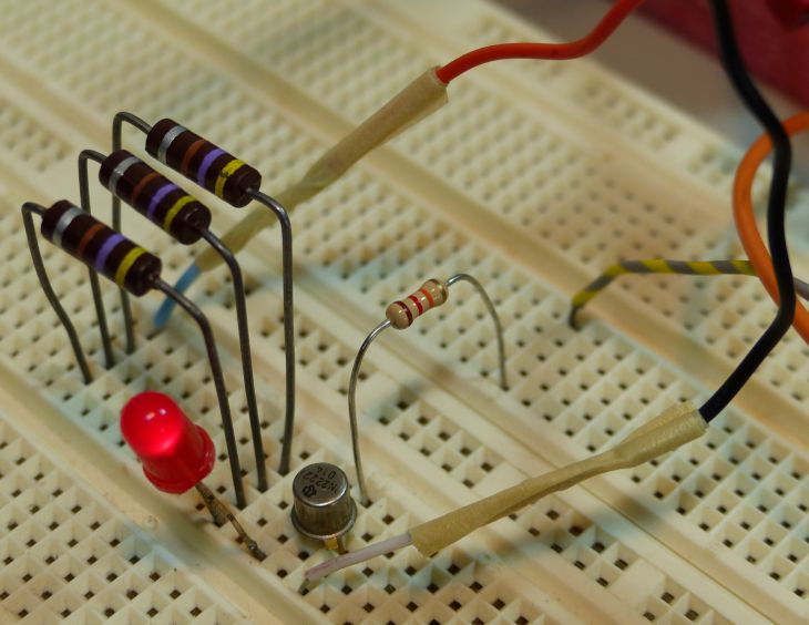
Let’s recap what we need:
– a red LED
– a 2N2222 transistor
– a 12000 ohm resistor (for the base)
– three 470 ohm resistors for the LED.
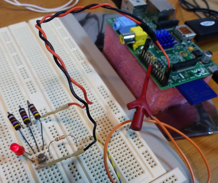
The final circuit is:
2 – The Software Side
There are several options to program the GPIO on the Raspberry Pi. You can, for example, use the wiringPi C library or you can use the RPi.GPIO Python module. Both solutions work fine.
I’m going to show a new way to code the GPIO using GeeXLab (formerly GLSL Hacker). The latest iteration of GLSL Hacker (v0.8.4.0) comes with a new library that makes it possible to program Raspberry Pi GPIO pins. This library called gh_rpi is available for Lua and for Python. gh_rpi is based on wiringPi so if you already know it, you will use gh_rpi in no time.
Now if you don’t want to use gh_rpi, you can still use RPi.GPIO. Remember that GLSL Hacker GeeXLab supports Python programming, then you can play with RPi.GPIO without problem.
The gh_rpi lib is simple to use. Here is a code snippet in Lua that shows to set to HIGH the pin 23 (in GPIO pin numbering mode, or pin 16 in physical pin numbering mode).
-- Set the pin 23 mode: output
--
local GPIO_INPUT_MODE = 0
local GPIO_OUTPUT_MODE = 1
gh_rpi.gpio_set_pin_mode(23, GPIO_OUTPUT_MODE)


-- Set the pin 23 to HIGH state
--
local LOW = 0
local HIGH = 1
gh_rpi.gpio_digital_write(23, HIGH)


-- Set the pin 23 to LOW state
--
gh_rpi.gpio_digital_write(23, LOW)
That’s all we need to know to play with the LED in GLSL Hacker GeeXLab. Complete demos are available in the code sample pack in the gles2/rpi_gpio/ folder (demo_v2_blinking_led.xml). You can download GeeXLab for Raspberry Pi as well as the code sample pack from THIS PAGE.
Remark: theses demos must be launched with root rights:
$ sudo GLSLHacker_RPi /demofile="...."
 The blinking LED demo: the red square shows when the LED is ON or OFF
It looks as though you have a typo in your math in sec. 1.2. When computing the proper resistance for the collector circuit with the LED, you use the formula:
Rb = (5.0 – 1.8 – 0.7) / 20mA = 145 ohm0.7V is the emitter-base voltage. The emitter-collector voltage is 0.3V for the 2n2222 according to your discussion. Shouldn’t this be used in your analysis of the proper resistance in series with the LED, and for the subsequent formula:
Ic = Iled = (5.0 – 1.8 – 0.7) / 470 = 6mAfor computing the current through the LED?
It looks to me as if the proper computation should be:
Rb = (5.0 – 1.8 – 0.3) / 20mA = 145 ohmand
Ic = Iled = (5.0 – 1.8 – 0.3) / 470 = 6mAYour computations are correct if you assume that you meant 0.3V instead of 0.7V for the e-c voltage, but not so if you do the same computations with 0.7V as you have specified in your discussion.
Absolutely it’s a typo, 0.3V is the right value in the equations. Thank you for the feedback Lindsay!